LUC POWER DISTRIBUTION BOARD
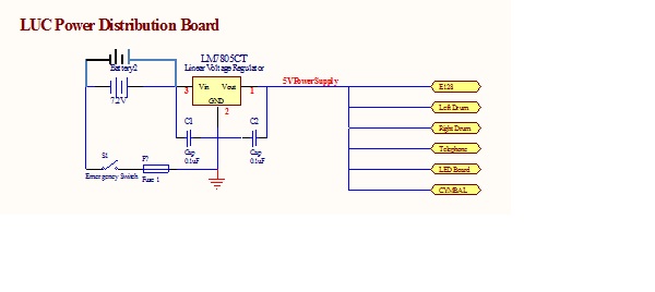
From a 7.1V (full charge 8.5V) NiCd battery 5V regulated output was required to supply to all the components. For this purpose LM7805CT is used since it operates in the 7V- 12V range.
The current drawn by peripheral components on LUC is
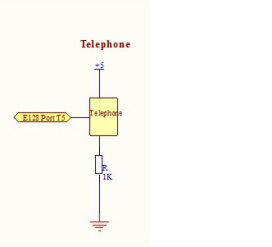
- 0.005A for Telephone
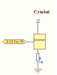
- 0.005 for Cymbal switch
- 0.016A for LEDs
- 0.01A for Microphones0.0002A for the PIC
The NiCd battery has 1500mA capacity, hence for surviving 8hrs two batteries were used.
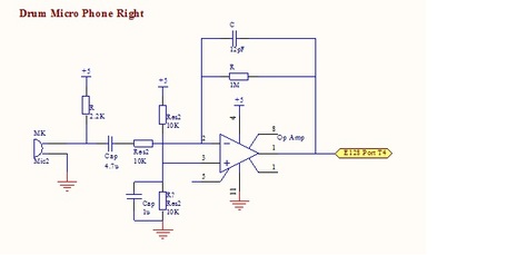
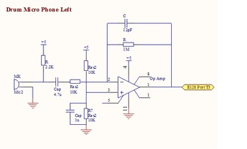
Drums circuit
|
|
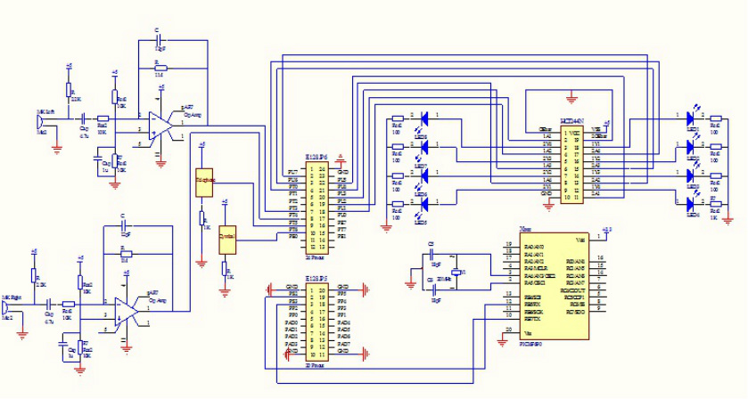
The circuits are designed as per the standard test circuit for the microphone EE-99-R. The operating voltage range of this microphone is 1.5V to 12V. The gain required was 100 and since the LM324N has a typical voltage gain of 100 it is chosen as the amplifier. For a gain of 100, Rf / Ri =100 . The resistors Rf, Ri chosen to satisfy this condition are 1M and 10K respectively. For a Vref of 2.5V two resistors of same value 10K each are used.
Speed control display Circuit
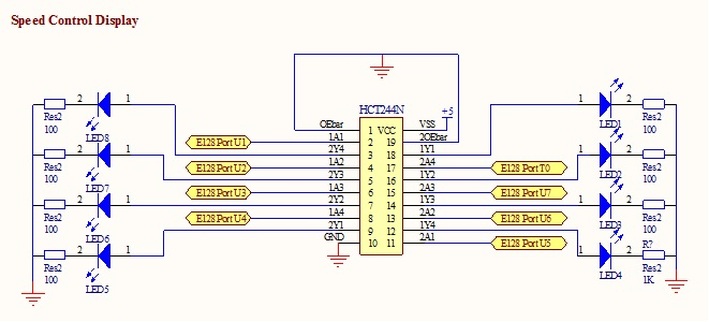
This circuit is used to glow the LEDs as shown in the figure below.

HCT244N is used to drive 8 LEDs. The Vout of HCT244N when high is Vcc and in this case 5V.
- Vf of the LEDs = 3V
- Max current = 20mA
- Rmin= 100 ohm
Cymbal Circut
Telephone Circuit
LUC OVERALL CIRCUIT
E128 PIN table
| JP6 Pin Label | JP6 Pin No. | Use | JP5 Pin Label | JP5 Pin No. | Use |
| NC | 1 | GND | 1 | ||
| PU7 | 2 | LED 7 | PS2 | 2 | Xbee Rx |
| PU6 | 3 | LED 6 | PS3 | 3 | Xbee Tx |
| PT0 | 4 | LED 8 | PP2 | 4 | |
| PT1 | 5 | PP0 | 5 | ||
| PT2 | 6 | PAD0 | 6 | ||
| PT3 | 7 | Drum left | PAD1 | 7 | |
| PT4 | 8 | Drum right | PAD2 | 8 | |
| PT5 | 9 | Telephone | PAD3 | 9 | |
| PT6 | 10 | Cymbal | GND | 10 | |
| PE0 | 11 | GND | 11 | ||
| NC | 12 | PAD7 | 12 | ||
| NC | 13 | PAD6 | 13 | ||
| PE1 | 14 | PAD5 | 14 | ||
| PT7 | 15 | PAD4 | 15 | ||
| PE7 | 16 | PP1 | 16 | ||
| PU0 | 17 | PP3 | 17 | ||
| PU1 | 18 | LED 1 | PP4 | 18 | |
| PU2 | 19 | LED 2 | PP5 | 19 | |
| PU3 | 20 | LED 3 | 20 | ||
| PU4 | 21 | LED 4 | |||
| PU5 | 22 | LED 5 | |||
| GND | 23 | ||||
| NC | 24 |
